
Types of Low RPM Motor Technologies and Their Applications
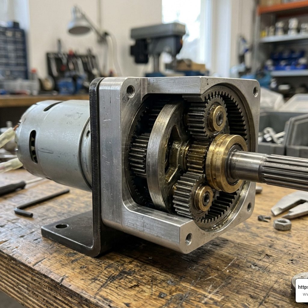
When selecting a low RPM motor, understanding the underlying drive technology is essential. Electric motors natively run at thousands of revolutions per minute (RPM). Achieving slow rotational speeds—typically defined as anything under 1,000 RPM, and often as low as 0.5 to 15 RPM—requires specific engineering approaches.
Different low-speed motor technologies serve distinct mechanical and industrial requirements:
- Gear Motors: These combine a standard electric motor core with an integrated internal gearbox (spur or planetary gears). The gear reduction ratio directly scales down the speed while multiplying torque. Compact units, such as a 3.5RPM 12V Low Noise DC Gear Motor with Metal Gears – Grade A in Electro Boat – Online electronics Components Store, use full-metal gear trains to deliver steady rotation under resistive loads in robotics and automated mechanisms.
- Synchronous Electric Motors: Operating on alternating current (AC), these motors maintain a rotational speed tied precisely to the power grid’s frequency (50 Hz or 60 Hz). Utilizing high-pole magnetic rotors, small AC synchronous motors run at low fixed speeds like 0.8/1 RPM or 5/6 RPM without complex controls. They are standard in craft cup turners, microwave oven turntables, and animated holiday displays.
- Worm Gear Assemblies: By setting a worm screw against a spur gear at a 90-degree right angle, worm gearmotors deliver high reduction ratios in a compact footprint. Models like the 31mm 12V 24V High Torque Low Speed DC Motor – Powerful provide up to 100 kg.cm of torque while supplying an inherent self-locking output shaft.
- Multi-Pole AC Induction Motors: Rather than using external mechanical gears, these industrial motors alter internal stator winding configurations to increase the magnetic pole count. As pole count increases, synchronous speed drops (e.g., a 2-pole motor at 50Hz runs at 3,000 RPM, a 6-pole runs at 1,000 RPM, and an 8-pole runs at 750 RPM). HVAC blowers frequently utilize multi-pole 48-frame configurations operating around 1,075 RPM across multi-speed tap settings.
From precision solar tracking systems that gradually adjust photovoltaic panels across the horizon to heavy industrial conveyors, agricultural feed mixers, and medical agitation devices, low-speed motors provide smooth motion across a wide array of fields.
AC vs DC Low RPM Motor Selection
Choosing between alternating current (AC) and direct current (DC) models shapes your power infrastructure and control options.
AC low RPM motors excel in continuous, fixed-speed industrial environments. Powered directly by single-phase 110V household supply or three-phase 380V industrial grids, they maintain steady speeds without internal brushes that wear out over time. Heavy machinery, such as a 1.5-4HP Low RPM AC Gear Motor 160mm from China manufacturer – SL TECH, uses multi-voltage support and dual 50Hz/60Hz grid compatibility to power CNC machine drives, petrochemical mixers, and packaging equipment quietly and reliably.
Conversely, DC low RPM motors are ideal for mobile, battery-operated, or dynamically controlled applications. Reversing a brushed DC motor is straightforward: simply swap the positive and negative supply wire polarities. Small DC gearmotors, like the Pololu – 34:1 Metal Gearmotor 25Dx67L mm LP 12V with 48 CPR Encoder, feature quadrature encoders for precise speed adjustment and closed-loop positional feedback.
To evaluate which power architecture fits your setup, review our technical breakdown on the AC motor vs DC motor differences.
Heavy-Duty Applications for Gearbox-Integrated Motors
In heavy-duty applications, high static weight or dynamic back-driving forces can destabilize standard motor shafts. Gearbox-integrated motors solve this issue by pairing high-load mechanical reduction assemblies with protective drive features.
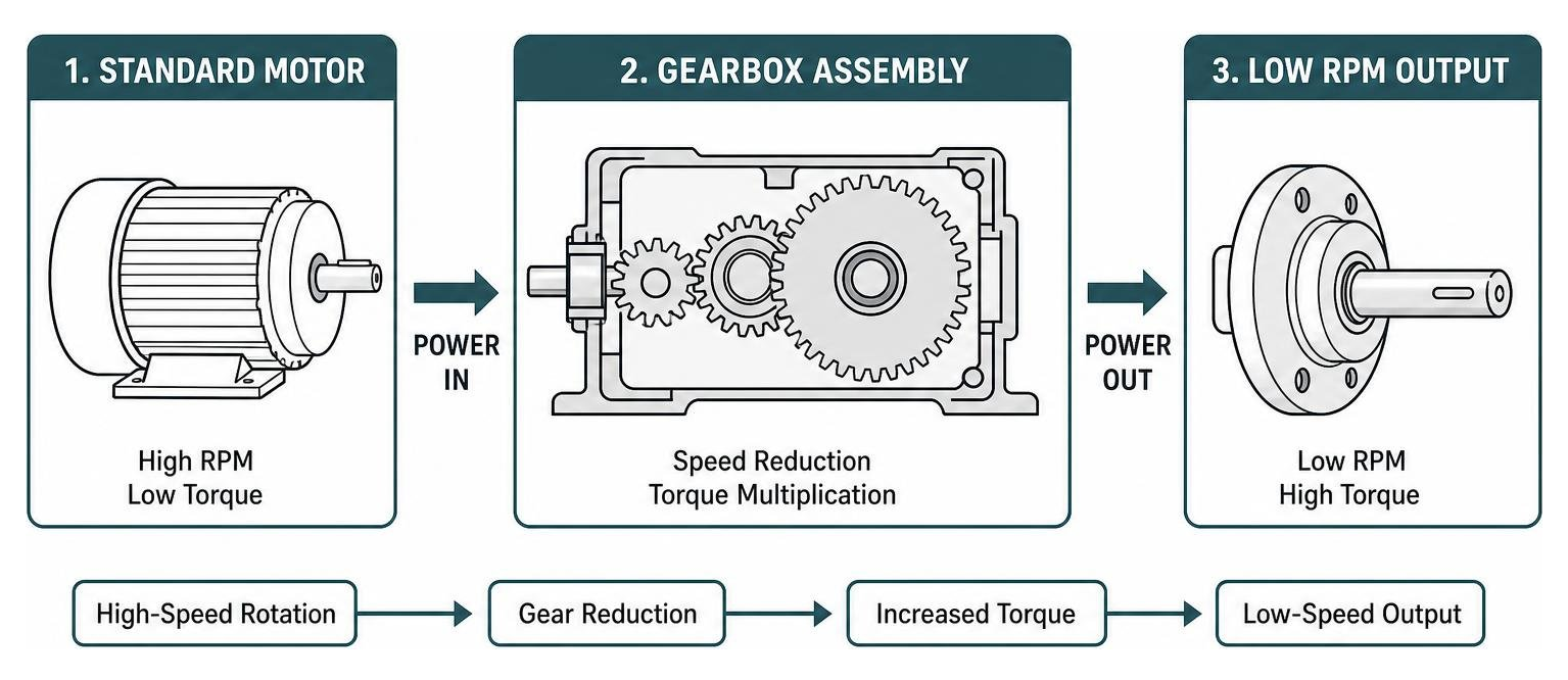
A key benefit of right-angle worm drive motors is their self-locking mechanism. Because a worm screw can turn the worm gear, but the gear cannot easily rotate the screw, the system locks up when power cuts off. This mechanical hold prevents heavy external loads from back-driving the motor.
Industrial equipment relying on gearbox-integrated slow-speed power includes:
- Automated Security Gates and Doors: Providing steady opening speeds while holding massive gate leaves against high wind resistance.
- Freight Elevators and Hoists: Supporting vertical dynamic human or machinery weights up to hundreds of pounds, requiring high starting torque and positional holding.
- Industrial Winches and Valves: Motors like the Low Speed High Torque Gearbox Motor 12V 5RPM For Heavy-Duty Applications | Custom Solutions | Etonm Motor manage heavy fluid flow or heavy structural pulling without overheating.
Key Technical Specifications for Selecting a Low RPM Motor
Selecting the proper low RPM motor requires matching electrical nameplate parameters to physical load demands. Under-sizing a motor leads to stalling and thermal burnout, while over-sizing increases cost and system complexity.
When evaluating candidate motors, analyze these core parameters:
- Operating Voltage and Current: Micro-robotics setups run on low DC ranges (2.0V to 4.0V), such as a high-speed 3.3V Micro DC Motor 14000RPM KC-N10-15.9-3.3V – Kechen Motor paired with external gearheads. Standard automation builds utilize 12V DC or 24V DC supplies, whereas industrial machinery operates on 110V, 220V, or 380V single- or three-phase AC power.
- Continuous Load Torque vs. Stall Torque: Torque represents rotational force (measured in kg·cm, oz·in, or Nm). Ensure the motor operates comfortably within its continuous load threshold. Running a brushed DC motor above 25% of its theoretical stall torque generates rapid thermal stress that damages internal brushes and field windings.
- Target RPM Range: Define whether your application requires a low fixed output speed (e.g., 3.5 RPM or 10 RPM) or variable speeds (e.g., 50 to 500 RPM via electronic drives).
- Output Shaft Configuration: Common mechanical couplings include 4mm or 6mm D-shafts, dual concentric shafts, keyways, and right-angle outputs. Shaft alignment prevents premature bearing destruction.
- Feedback Accessories: High-precision positioning systems require integrated magnetic quadrature encoders. Encoders track speed, direction, and revolution counts (e.g., 48 counts per revolution at the motor shaft multiplied across a 34:1 gear ratio yields 1,632.67 output CPR).
Torque Generation and Gear Reduction Mechanisms
How does a small electric motor generate hundreds of kilogram-centimeters of twisting force? The secret lies in basic physics and gear ratios.
$$Torque_{output} approx Torque_{motor} times Gear Ratio times Gearbox Efficiency$$
Because mechanical power is the product of rotational speed and torque, stepping down output speed through gear reduction proportionally multiplies delivered torque. A high-speed micro motor spinning at 14,000 RPM can drive a multi-stage spur or planetary gearbox to output a steady 5 RPM.
However, mechanical reduction introduces friction losses. While spur gearboxes offer high energy transmission efficiency (often 85% to 95%), right-angle worm drive assemblies incur higher friction, yielding efficiency rates between 40% and 75%. Designers must account for these gearbox losses when sizing input motor horsepower.
Cost Factors and Price Expectations
Low RPM motors vary widely in market price, depending on component quality, frame size, power ratings, and protective certifications:
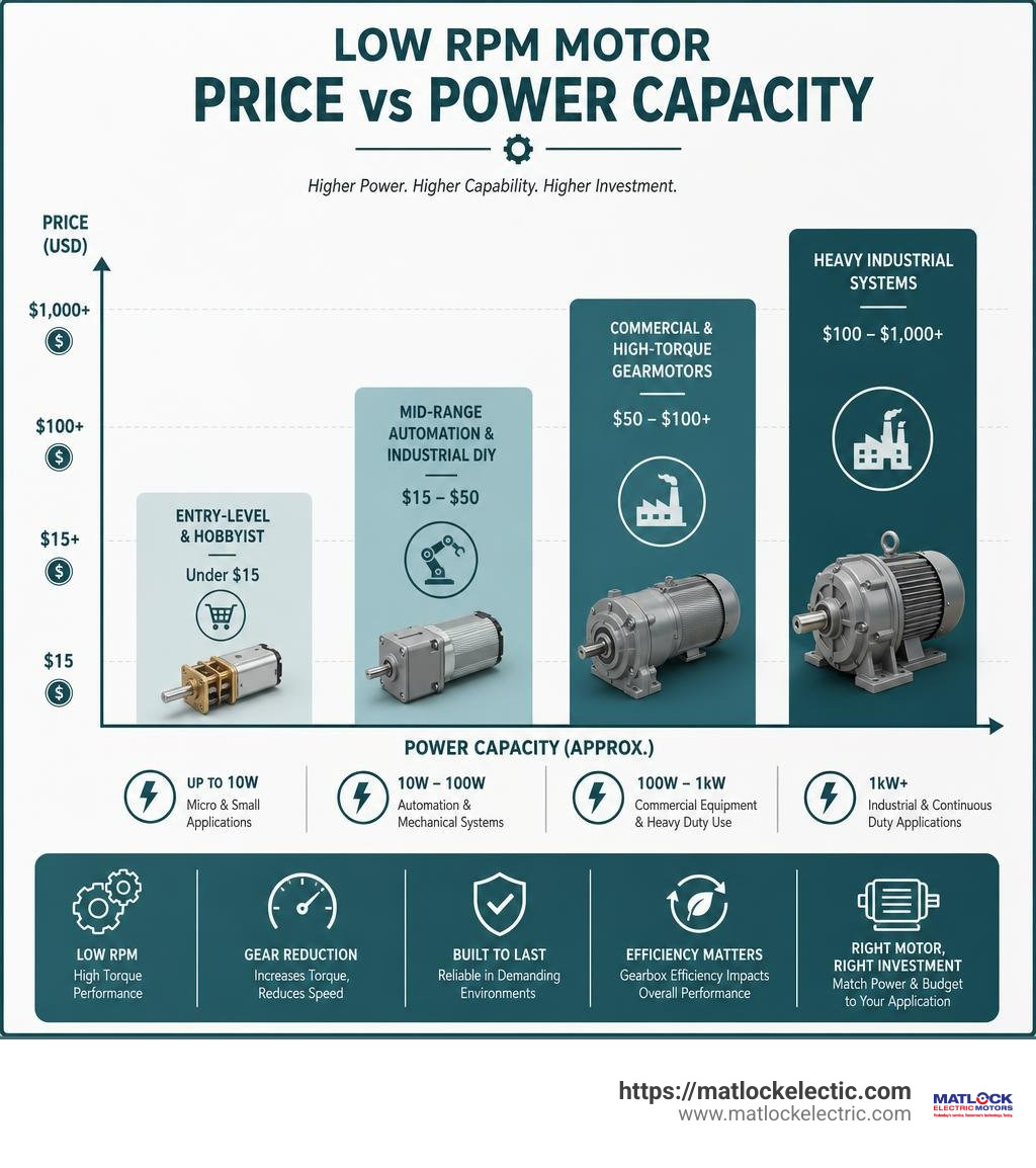
- Entry-Level & Hobbyist (Under $15): Compact AC synchronous motors (5–6 RPM, 4W, 110V) for craft cup turners or microwave turntables cost between $8.99 and $12.90. Simple 3V–6V DC micro N20 metal gear motors fall within this budget.
- Mid-Range Automation & Industrial DIY ($15 to $50): High-torque 12V/24V DC worm gear motors delivering 40 to 100 kg·cm output torque, as well as units with integrated dual-channel quadrature encoders, range from $20 to $45.
- Commercial & High-Torque Gearmotors ($50 to $100+): Premium AC gear-reducer motors (e.g., 6W to 25W setups with matching variable-speed dial controllers) cost between $75 and $92. Continuous-duty HVAC furnace blowers in standard 48-frame sizes average around $89.99.
- Heavy Industrial Systems ($100 to $1,000+): Large multi-horsepower multi-stage AC gearmotors featuring 160mm rotors, food-grade anti-corrosion surface treatments, and IP-rated enclosures represent higher-end capital investments tailored for continuous manufacturing lines.
Control, Wiring, and Performance Management
Operating a low RPM motor safely requires proper electrical control interfaces. Connecting a low-speed motor directly to mains power without protection or proper speed controllers can cause premature motor failure or unsafe operational conditions.

Speed Control Methods
Depending on whether your low RPM motor runs on AC or DC power, speed management requires specific control mechanisms:
- DC Pulse-Width Modulation (PWM): Instead of dropping supply voltage through energy-wasting resistors, PWM rapidly switches supply voltage on and off thousands of times per second. Adjusting the duty cycle (the ratio of ON time vs. OFF time) regulates motor RPM while maintaining high shaft torque.
- Variable Frequency Drives (VFDs): For AC low RPM induction gearmotors, VFDs adjust the rotational speed by varying the electrical frequency (Hz) delivered to the motor windings. A VFD allows a standard AC gearmotor to scale smoothly between 50 RPM and 500 RPM without torque loss or erratic thermal behavior.
- Polychronic Phase Switching & Relays: AC synchronous motors maintain precise speed based on supply frequency. Altering rotation direction on small AC units often requires capacitor-assisted phase-shifting wiring or mechanical anti-reverse detents built into the gear housing.
Wiring and Reversing Circuits
Reversing direction and regulating speed on DC gearmotors is usually accomplished through an H-Bridge circuit (such as an L298N driver module). By toggling digital control pins on a microcontroller, an H-bridge flips the polarity delivered to output terminals:
For advanced motion systems, visit our specialized resource on industrial Drives and Controls.
Pros and Cons of a Dedicated Low RPM Motor vs. Speed Controllers
Engineers often face a design choice: Should you buy a native low RPM motor (or gearmotor), or run a standard high-speed motor turned down low with a speed controller?
| Feature / Factor | Dedicated Low RPM Motor / Gearmotor | Standard High-Speed Motor + Speed Controller |
|---|---|---|
| Low-Speed Torque | High: Mechanical gear reduction multiplies torque output. | Low: Electronic throttling drops speed but weakens shaft torque output. |
| Thermal Dissipation | Excellent: Low operating speeds and mechanical ratios prevent overheating. | Poor: Reduced fan speed at low RPM causes heat buildup in motor windings. |
| Energy Efficiency | Optimized: Operates near peak electrical efficiency curve. | Inefficient: High power draw relative to mechanical work performed at low speeds. |
| System Complexity | Low: Plug-and-play mechanical installation. | High: Requires external drives, heat sinks, and feedback wiring setup. |
| Holding Force | Self-Locking: Worm gear models lock mechanically when power is off. | None: Shaft spins freely when unpowered unless an external brake is added. |
For applications demanding high force at low speeds, dedicated low RPM gearmotors are consistently more efficient, produce less heat, and offer better operational reliability.
Safe Installation and Maintenance Guidelines
Proper physical setup and ongoing maintenance keep low-speed equipment operating reliably over a long service life:
- Axial and Radial Load Protection: Output shafts are engineered to handle specific rotational loads. Heavy vertical dynamic loads can cause shaft bending and gear misalignment. Always integrate tapered roller bearings or dedicated thrust bearings to isolate axial forces from the motor faceplate.
- Mounting Fastener Depth: When securing face-mount gearmotors, pay close attention to mounting screw lengths. Screws threaded more than 6mm (0.24 inches) into the gearbox faceplate can contact and destroy internal precision gears.
- Thermal Clearance: Keep motor housings clean and clear of dust buildup to allow effective thermal dissipation. Even low RPM motors require adequate airflow across their frame to prevent coil deterioration.
- Gearbox Lubrication Intervals: Metal gearboxes require clean lubrication. Replace industrial gear oil every 6 months under standard 8-hour daily operation, or every 3 months for heavy 24/7 continuous duty cycles. For hygienic environments like food packaging lines, apply food-grade anti-corrosion coatings and approved synthetic lubricants.
- Electrical Grounding: Ensure metal motor frames are bonded to system ground connections to prevent static buildup and protect sensitive control circuits.
Explore our complete catalog of industrial options by reviewing our guide to Electric Motors.
Frequently Asked Questions About Low Speed Motors
How does a low RPM motor generate high torque without overheating?
A dedicated low RPM motor relies on mechanical advantage or multi-pole electrical designs rather than current throttling. By pairing a high-speed internal rotor with a mechanical gear reduction assembly, rotational velocity steps down while output torque multiplies proportionately.
Because the internal motor runs within its optimal efficiency window, energy is converted into mechanical work rather than wasted heat. In direct-drive multi-pole AC motors, increasing the stator magnetic pole count lowers the synchronous rotational speed natively, reducing low-frequency thermal stress on electrical windings.
Can you reverse the rotation direction of a low speed motor?
Yes. Reversing direction depends on the motor’s underlying power configuration:
- Brushed DC Motors: Reverse the polarity of the positive and negative power supply leads. This can be handled mechanically using a DPDT switch or electronically via an H-bridge driver circuit.
- Three-Phase AC Motors: Swap any two of the three incoming phase power lines (U, V, W).
- Single-Phase AC Synchronous Motors: Use external phase-shifting capacitors paired with directional control switches, or rely on built-in directional gear detents.
What maintenance do low speed gear motors require over time?
While low RPM motors experience less surface wear than high-speed motors, long-term operational health requires routine maintenance:
- Lubrication Checks: Periodically inspect gear grease or oil levels. Replace gear oil every 3 to 6 months depending on daily operating hours.
- Gear Tooth & Bearing Inspection: Listen for acoustic changes or gear chatter, which point to worn gear teeth or dry bearings.
- Housing Cleanliness: Wipe away accumulated dust, industrial grit, or chemical residue from housing vents to maintain proper thermal cooling.
When gearboxes wear down or motor windings require testing, learn more about specialized industrial motor Repair.
Conclusion
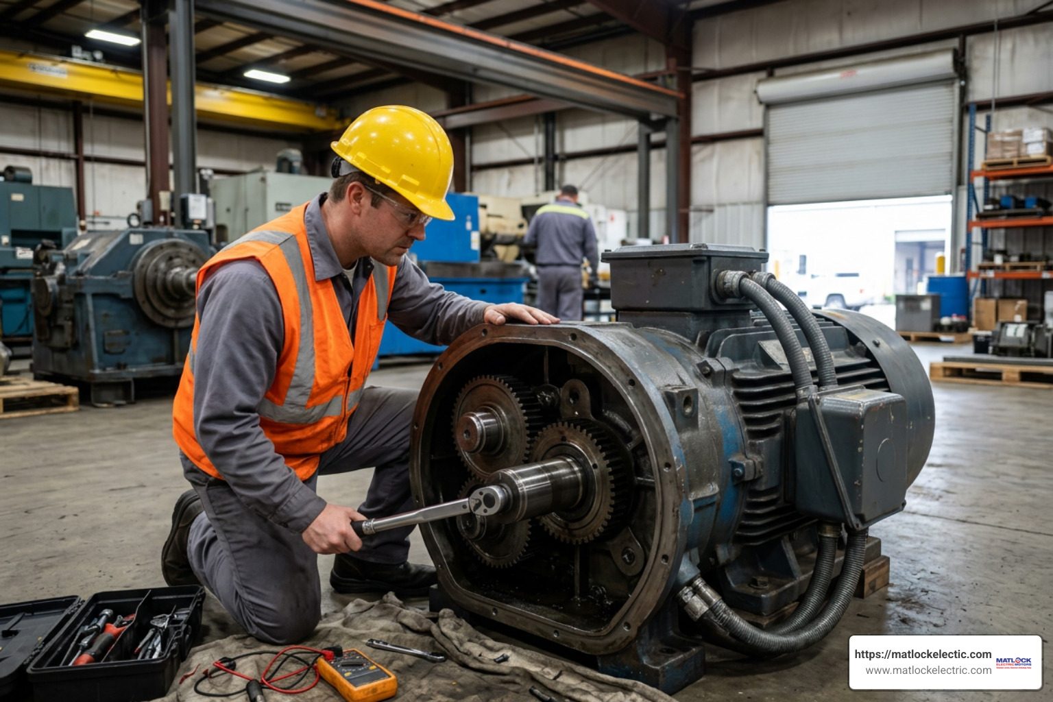
Finding the ideal low RPM motor comes down to clear mechanical priorities: identify your operating voltage, calculate continuous load torque, verify target RPM limits, and select a gearbox topology suited to your structural footprint.
Whether you need a compact DC worm gear motor to hold a dynamic load safely in place or a continuous-duty AC gearmotor to run an industrial production conveyor, choosing purpose-built low-speed hardware yields quiet operation, low mechanical wear, and high energy efficiency.
When sizing specialized low-speed drives or servicing critical industrial motors, work with experienced motion control professionals. Explore dedicated engineering services and high-performance equipment through our Electric Motor Solutions at Matlock Electric.