
DC Motor Armature Resistance: The Quick Answer
DC motor armature resistance is the electrical resistance of the armature winding circuit, including the winding and, in practical terminal tests, brush and commutator contact resistance. It is usually very low, but it has a major effect on starting current, heat, speed drop, torque, and motor efficiency.
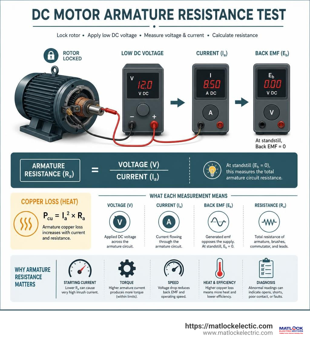
For an accurate bench value, do not rely only on a basic ohmmeter reading. Lock the rotor, apply a safe low DC voltage for a brief test, measure voltage and current, then calculate:
Armature resistance = voltage / current
At standstill, back EMF is zero, so this voltage-drop method measures the total armature circuit resistance more reliably than a low-current meter test.
| What resistance affects | Why it matters |
|---|---|
| Starting current | Low resistance can cause a very high current surge at zero speed. |
| Torque | Higher armature current produces more torque, up to the motor’s safe limit. |
| Speed | Resistance creates voltage drop, reducing the voltage available to generate back EMF and maintain speed. |
| Heat and efficiency | Armature copper loss equals Ia squared x Ra, so resistance creates heat under load. |
| Diagnosis | Uneven, very high, or near-zero readings can point to opens, shorts, poor brush contact, or grounding faults. |
The key is context. A low reading may be normal for a larger, high-current motor. A reading that changes sharply between commutator positions, or differs from expected test results, may signal an armature problem rather than a healthy low-resistance circuit.
What Is DC Motor Armature Resistance and Why Is It Critical?
When we evaluate the internal electrical pathways of a direct current machine, DC motor armature resistance ($R_a$) represents the total ohmic opposition encountered by current passing through the armature circuit. This circuit encompasses the heavy copper coils wound around the rotating iron core, the commutator segments, the carbon brushes, and the connecting leads.
Because armature windings are designed to carry high working currents while producing strong electromagnetic torque, they are constructed from thick wire with very low internal resistance—frequently under 1 ohm in medium to large industrial machines. However, even fractions of an ohm play a massive role in motor performance. If you are comparing operating traits across different electrical machines, understanding the Differences of AC & DC Motors highlights how direct current armatures rely so heavily on low DC resistance to establish operational torque.
Voltage Equation and Back EMF Dynamics
To see how DC motor armature resistance dictates steady-state operation, we look at the fundamental voltage balance equation of a DC motor:
$V = Eb + (Ia times R_a)$
Where:
- $V$ is the line terminal voltage applied across the motor leads.
- $Eb$ is the back electromotive force (back EMF) induced in the rotating armature conductors as they cut through magnetic flux ($Eb = k cdot Phi cdot omega$).
- $I_a$ is the armature current.
- $R_a$ is the total armature circuit resistance.
When the shaft rotates, the induced counter-EMF ($Eb$) opposes the supply voltage, limiting the net voltage across the copper windings to $(V – Eb)$.
Consider a standard scenario: a 200-V DC motor with an armature resistance of 0.5 $Omega$ drawing an armature current of 20 A under load. The voltage drop across the armature resistance is $Ia times Ra = 20text{ A} times 0.5 Omega = 10text{ V}$. Subtracting this 10 V drop from the 200 V supply gives an induced back EMF of 190 V.
In a much larger 240-volt, 10-horsepower motor running at rated speed and drawing 38 amperes at full load, the internal armature resistance might be a mere 0.06 ohm. At full load, its internal armature voltage drop is only $38text{ A} times 0.06 Omega = 2.28text{ V}$, leaving a counter EMF of 237.72 V. You can quickly plug your own motor nameplate values into an Online Armature Resistance Calculator to see how back EMF changes under varying mechanical loads.
Influence on Starting Current and Motor Starters
The low value of DC motor armature resistance presents a significant challenge when energizing a stationary motor. At the exact moment power is applied (standstill), the armature shaft rotational speed ($omega$) is zero. Because speed is zero, back EMF ($E_b$) is completely absent ($0text{ V}$).
Without back EMF to counter the line voltage, the initial current surge ($I_{text{start}}$) is limited solely by the tiny armature resistance:
$I_{text{start}} = frac{V}{R_a}$
For example, take a 110-V DC shunt motor with an armature resistance of 0.3 $Omega$. If connected directly to line voltage at standstill without protection:
$I_{text{start}} = frac{110text{ V}}{0.3 Omega} = 366.67text{ A}$
A starting surge of nearly 367 amperes can instantly trip upstream circuit breakers, damage commutator bars, or vaporize brush contacts. To prevent direct-on-line current spikes, technicians install a motor starter that inserts temporary series resistance into the armature circuit. Adding 7.03 $Omega$ of external starting resistance caps the initial starting current to a safe 15 A ($110text{ V} / (0.3 Omega + 7.03 Omega) = 15text{ A}$). As the motor accelerates and builds back EMF, the starting resistor steps down until the motor operates cleanly across its native armature winding. You can review a detailed academic numerical analysis in this Solved DC Motor EMF Example.
Bench Testing: How to Measure DC Motor Armature Resistance
When maintenance crews attempt to measure DC motor armature resistance on a shop bench, they often run into confusing discrepancies. Standard diagnostic tools frequently provide false readings due to the unique electro-mechanical properties of brush-to-commutator interfaces.
Why Multimeter Resistance Readings Are Misleading
Using a standard digital multimeter (DMM) set to the low-ohms range across the motor leads $A1$ and $A2$ will almost always yield inaccurate or excessively high resistance values on brushed DC motors.
A standard multimeter applies tiny excitation voltages (typically less than 1.5 V) and test currents measured in microamps or a few milliamps. However, carbon brushes riding on copper commutator bars develop a non-linear oxide and graphitic contact film during operation. This oxide boundary layer requires adequate voltage and current to break down and establish low-resistance electrical conduction.
Because a multimeter lacks the voltage and current necessary to penetrate this graphitic oxide film, the meter measures high contact resistance along with the winding resistance.
For instance, during bench tests on a small 24 VDC permanent magnet motor, a digital multimeter recorded a static lead resistance of 0.674 $Omega$. However, when subjected to proper dynamic voltage-drop testing, the actual armature circuit resistance was calculated to be just 0.196 $Omega$. On a 130 VDC motor, a multimeter measured 11.41 $Omega$ while true circuit testing revealed 11.13 $Omega$. The low-voltage DMM error is especially severe in low-voltage, high-current armatures.
Measuring DC Motor Armature Resistance via Locked-Rotor Testing
To bypass brush film contact errors and get a precise value for DC motor armature resistance, we perform a low-voltage locked-rotor test (also called the voltage-drop method).

Here is our step-by-step bench testing procedure:
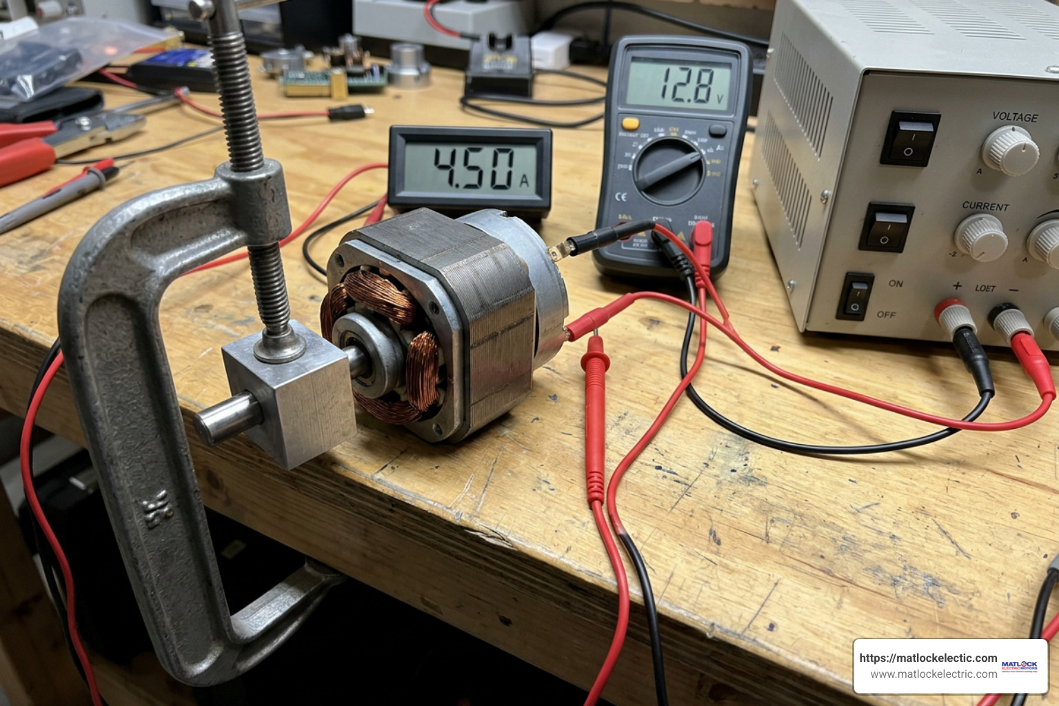
- Secure the Shaft Firmly: Mechanically clamp or lock the motor armature shaft to ensure zero rotation during testing. Locking the rotor guarantees speed $omega = 0$, forcing back EMF to remain exactly zero ($E_b = 0text{ V}$).
- Connect a Variable DC Power Supply: Wire a current-limited, adjustable DC power supply across the armature terminals ($A1$ and $A2$). Place a calibrated inline DC ammeter in series and a precision voltmeter directly across the motor terminal studs.
- Apply Low Test Voltage: Slowly turn up the DC power supply voltage from zero until the ammeter reads at least 10% of the motor’s rated nameplate current (or a minimum of 0.25 A for small fractional-horsepower units). Keeping current modest prevents rapid thermal rise in copper wire during testing.
- Record Voltage and Current: Quickly note the terminal voltage ($V$) and armature current ($I_a$).
- Calculate Static Resistance: Apply Ohm’s Law: $Ra = frac{V}{Ia}$.
- Sample Multiple Angular Positions: Rotate the locked armature shaft manually to five or six distinct rotational angles around the 360-degree commutator sweep and repeat the test. Averaging these calculated readings accounts for minor bar-to-bar contact variations.
Advanced Winding Diagnostics and Fault Identification
Routine resistance measurements serve as our primary window into winding health. When physical stress or thermal overload degrades insulation performance, taking careful resistance readings across individual coils helps pin down internal faults before catastrophic failure occurs. If you suspect deeper coil breakdown, our team provides comprehensive bench testing and winding overhauls through our dedicated DC Repairs division.
Diagnostic Tests for Open Circuits and Coil Shorts
When diagnosing an uninstalled armature removed from its motor frame, a simple visual check is not enough. Technicians perform three targeted electrical resistance tests across the exposed copper commutator bars:
- The 180-Degree Pairwise Resistance Test: Place meter probes on commutator bars located directly opposite each other ($180^circ$ apart). Work systematically around the full circumference of the commutator. Every pairwise reading should match within a tight tolerance (typically $pm 2%$). A sudden drop in resistance indicates internal turn-to-turn short circuits, while a huge spike or open circuit reading reveals a burned or broken copper conductor.
- The Bar-to-Bar Resistance Test: Measure resistance across adjacent commutator bars (e.g., Bar 1 to Bar 2, Bar 2 to Bar 3). This tests individual coil loops in the winding scheme. Equal resistance across all adjacent bars confirms balanced coil construction.
- The Stack Insulation (Ground) Test: Touch one test probe firmly to a clean copper commutator bar and press the second probe against the laminations of the grounded iron armature stack or central steel shaft. The meter must register infinite resistance ($MOmega$ or $O.L.$). Any measurable continuity proves that ground insulation has broken down, shorting the copper winding to the frame.
Comparing Armature Resistance Across Motor Configurations
Measuring resistance also allows technicians to quickly identify unlabelled industrial DC motor types. Field windings and armature circuits feature vastly different conductor sizes and turn counts depending on whether the machine is wired in shunt, series, or compound configurations.
| Motor Type | Armature Resistance ($R_a$) | Series Field Resistance ($R_{se}$) | Shunt Field Resistance ($R_{sh}$) | Typical Terminal Markings |
|---|---|---|---|---|
| Shunt Wound | Very Low ($0.05 – 5.0 Omega$) | None | High ($50 – 200 Omega$) | $A1-A2$, $F1-F2$ |
| Series Wound | Low ($0.1 – 2.0 Omega$) | Low ($0.1 – 1.5 Omega$) | None | $A1-A2$, $S1-S2$ |
| Compound Wound | Low ($0.1 – 3.0 Omega$) | Low ($0.05 – 1.0 Omega$) | High ($40 – 180 Omega$) | $A1-A2$, $S1-S2$, $F1-F2$ |
| Permanent Magnet (PMDC) | Low to Med ($0.2 – 14.0 Omega$) | None (Permanent Magnets) | None | $A1-A2$ or $(+)/(-)$ Leads |
Notice that shunt fields consist of many turns of fine wire, resulting in high resistance to limit field current when wired directly across line voltage. In contrast, series field windings consist of a few turns of heavy wire designed to carry full armature current, yielding very low resistance similar to the armature itself. Technicians can review standard shop protocols in this Field and Armature Resistance Measurement Protocol. For additional field guide steps on terminal tracing, read How to Identify DC Motor Type: Series, Shunt, Separately Excited – Industrial Monitor Direct.
Impact on Motor Performance, Speed Control, and Efficiency
Beyond starting dynamics, DC motor armature resistance directly influences operational speed regulation, internal thermal losses, and overall machine efficiency under varying mechanical loads.
DC Motor Armature Resistance Control for Speed Regulation
The steady-state speed ($omega$ in radians per second or $N$ in RPM) of a DC motor is expressed by rearranging its voltage and electromotive equations:
$N = frac{V – (Ia cdot Ra)}{k cdot Phi}$
Where $k$ is the motor structural constant and $Phi$ is the magnetic field flux.
This relationship forms the basis of armature resistance speed control. By placing a variable heavy-duty series resistor ($R_{text{ext}}$) into the armature circuit, we deliberately increase total circuit resistance to $(Ra + R{text{ext}})$.
Adding external resistance increases the internal voltage drop ($Ia times [Ra + R_{text{ext}}]$), reducing the voltage available to generate back EMF. As a result, the motor slows down below its rated base speed.
While this speed control method is simple, it comes with a major downside: high power loss. Heavy armature current flowing through $R_{text{ext}}$ dissipates substantial heat ($Ia^2 cdot R{text{ext}}$), making armature resistance control inefficient compared to modern electronic drives.
For instance, in a 200V DC series motor with $Ra = 0.1 Omega$ and series field $Rf = 0.15 Omega$ running at 600 RPM with 28 Nm of shaft torque, internal copper losses ($Ia^2 [Ra + R_f]$) combine with mechanical friction losses (such as 251.3 W) to dictate output efficiency. You can examine complete current calculations using this Calculations for Series Motor Current tool, or work through step-by-step circuit problems in this guide on Solving Motor Performance Questions.
Motor Scale Effects: Large vs. Small Armature Resistance
A clear pattern emerges when measuring armature resistance across motors of different physical sizes: physical motor dimensions inversely scale with internal resistance.
- Small PMDC Motors (e.g., fractional HP, hand-held equipment): These utilize thin gauge copper wire wound with many turns to build necessary magnetic strength in tiny frames. Consequently, smaller DC motors exhibit higher armature resistance, typically ranging from 4.5 $Omega$ to 14 $Omega$. A small 100-V DC motor with an armature resistance of 10 $Omega$ driving a constant-torque load at 1000 RPM consumes 250 watts of input power.
- Large Industrial DC Motors (e.g., 10 HP to 500+ HP): High-power industrial armatures demand heavy current to deliver hundreds of foot-pounds of torque. They are constructed with thick copper conductors, larger slot cross-sections, and fewer turn loops. Therefore, large adult-hand-sized or frame-sized motors maintain low armature resistance, typically between 0.05 $Omega$ and 0.5 $Omega$ (and often well under 0.1 $Omega$).
Frequently Asked Questions About DC Motor Armature Resistance
Why do larger DC motors have lower armature resistance than smaller motors?
Larger industrial DC motors use heavy-gauge copper conductors with large cross-sectional areas and fewer physical turn loops per slot. Because conductor resistance is inversely proportional to cross-sectional area ($R = rho cdot frac{L}{A}$), thick wire drastically lowers internal resistance. This low resistance allows high-horsepower armatures to carry hundreds of amperes without excessive internal voltage drop or thermal breakdown.
Can you test armature resistance without removing the motor brushes?
Yes, but only if you use a locked-rotor voltage-drop test rather than a multimeter resistance mode. Applying a controlled low DC voltage (supplying at least 10% of rated nameplate current) breaks through the brush-to-commutator oxide film barrier, allowing you to accurately measure total armature circuit resistance right across terminals $A1$ and $A2$.
What causes armature resistance to increase during operation?
Armature resistance increases primarily due to thermal rise in the copper conductors during operation. Copper has a positive temperature coefficient of resistance ($alpha approx 0.00393 / ^circtext{C}$). As armature windings heat up under continuous load from room temperature ($25^circtext{C}$) to an operating temperature of $105^circtext{C}$, internal resistance rises by over 30%. High resistance can also stem from loose lead terminal connections, oxidized commutator bars, or worn carbon brushes making poor contact.
Conclusion
Understanding DC motor armature resistance is essential for maintaining and diagnosing industrial direct current machinery. From predicting initial locked-rotor current surges to evaluating internal copper losses ($Ia^2 Ra$), resistance measurements give us clear insight into motor health. Simple multimeter checks can be deceptive due to brush contact film—accurate diagnostic testing requires locked-rotor bench procedures using a controlled DC power supply.
If your plant’s equipment shows signs of electrical breakdown, shorted commutator bars, or insulation failure, rely on experienced motor specialists to restore equipment reliability. Explore our full range of Industrial Electric Motor Services to keep your plant machinery operating at peak performance.