
Why a Motor Winding Resistance Test Matters
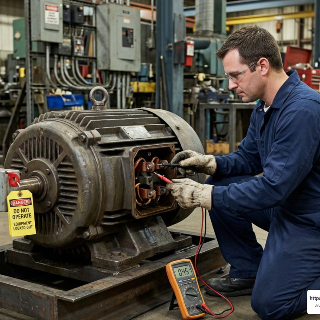
A motor winding resistance test checks whether the motor’s copper windings and electrical connections have a consistent, low-resistance path for current. It is a fast, useful way to find signs of an open winding, shorted turns, loose terminals, damaged leads, or high-resistance connections before they become heat, lost efficiency, or an unexpected shutdown.
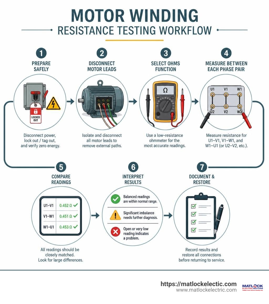
For a quick check, disconnect and lock out the motor, discharge stored energy, then measure resistance between each phase pair. The readings should be closely matched. A large difference between phases calls for further diagnosis, especially when the motor has a history of overheating, tripping, vibration, or poor starting performance.
| What to check | What a concerning reading may suggest |
|---|---|
| Infinite resistance between expected winding terminals | Open winding, broken lead, or failed connection |
| One phase reading much lower than the others | Possible shorted turns or wiring fault |
| One phase reading much higher than the others | Loose, corroded, or damaged connection |
| More than 5% phase resistance imbalance | A condition worth investigating before return to service |
Resistance testing is not the same as insulation resistance testing. A megohmmeter checks insulation from the winding to ground, while a winding resistance test checks the DC resistance through the winding conductors themselves. A motor can pass an insulation test and still have a phase-balance problem inside its windings.
Temperature matters, too. Copper resistance rises by about 0.39% for every 1 degree C increase. That means readings taken on a warm motor cannot be compared fairly with readings from a cool motor unless the temperature is recorded and considered.
Understanding Motor Winding Resistance and Performance
Electric motor windings consist of carefully calculated loops of insulated wire (typically copper or aluminum) wrapped around stator slots or rotor cores. When voltage is applied, current flows through these coils, generating the electromagnetic fields necessary to create rotation and drive mechanical loads.
However, all real-world electrical conductors possess inherent physical resistance to electrical current. Understanding how this electrical resistance behaves under operational stress is fundamental to keeping your equipment running efficiently and reliable. Whether managing large industrial drives or performing comprehensive AC Repairs, evaluating winding health helps prevent minor electrical anomalies from developing into catastrophic mechanical breakdowns.
The relationship between resistance, current flow, and thermal dissipation is dictated by basic physical laws:
- $I^2R$ Losses (Joule Heating): As electrical current ($I$) passes through winding resistance ($R$), energy is lost as heat. If winding resistance increases due to poor splices or corroded terminals, heat generation skyrockets exponentially.
- Operating Efficiency: Increased thermal dissipation directly degrades overall operating efficiency. More power is consumed to generate the same mechanical output.
- Torque Output and Voltage Drop: Higher DC resistance inside motor coils creates internal voltage drops. Lower voltage across active coil segments weakens magnetic field intensity, reducing total torque capability.
- Excessive Current Draw: Conversely, internal inter-turn short circuits decrease total coil resistance, causing current draw to surge. This trips protective overload relays and thermal breakers.
Why Measure Winding Resistance
We perform a motor winding resistance test to verify the physical integrity of the internal copper conductors, internal splices, and terminal lead connections. Over time, electric motors endure heavy thermal cycling, mechanical vibration, moisture ingress, and chemical exposure. These environmental stresses degrade wire insulation and physical connections.
Measuring static direct current (DC) resistance provides a baseline measurement of motor health. By comparing field measurements against original manufacturer specifications or historical trends, we can assess whether thermal degradation has altered the conductor wire gauge, compromised internal solder points, or oxidized physical wire terminations.
Establishing baseline health measurements during initial commissioning ensures that future diagnostic tests catch subtle shifts in phase balance before thermal breakdown destroys slot insulation.
Faults Detected by Resistance Testing
While high-voltage insulation tests verify whether electricity stays inside the copper path, DC winding resistance tests evaluate the condition of the conductive path itself. Performing regular resistance checks allows us to detect several critical internal anomalies:
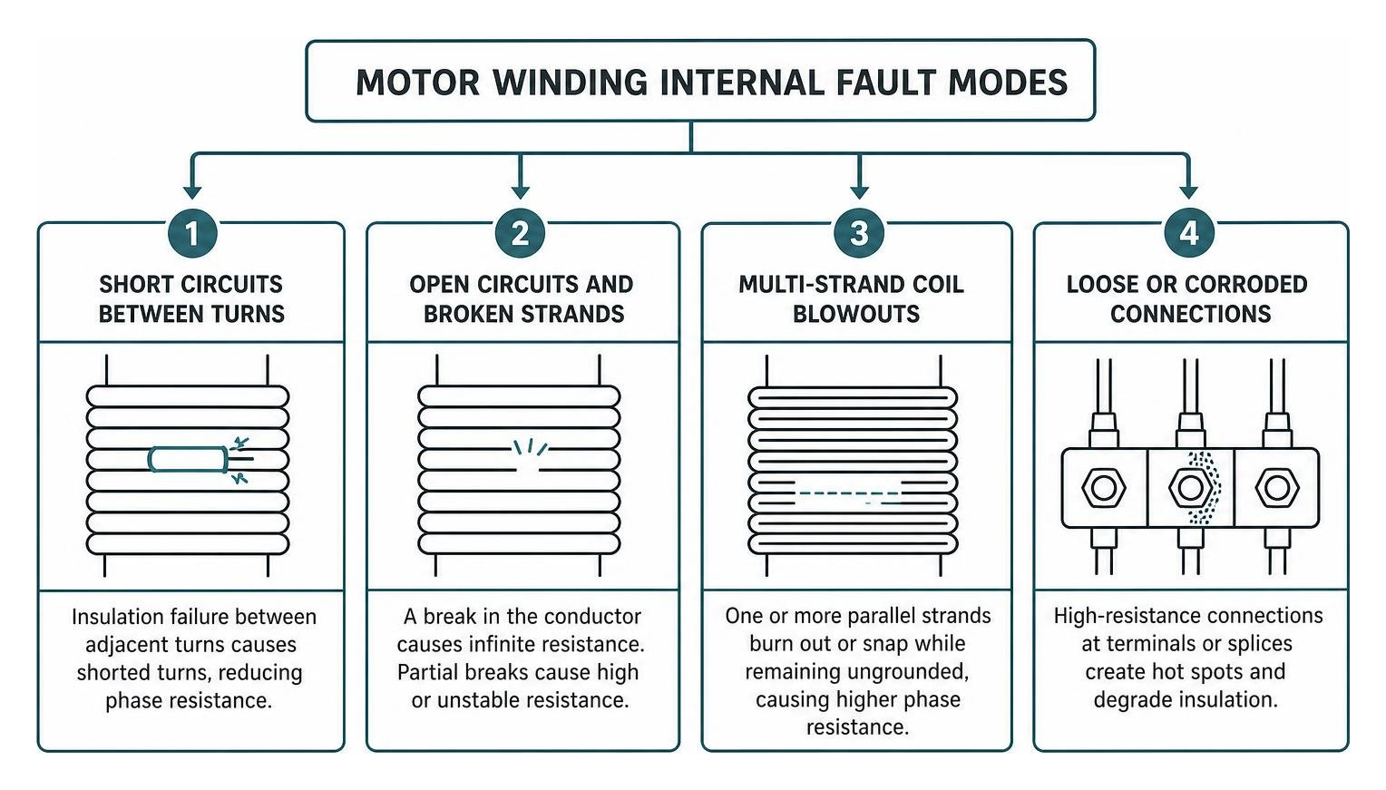
- Short Circuits Between Turns: When wire insulation degrades within a single phase coil, adjacent turns short together. This reduces total phase resistance and destroys the balanced magnetic field needed for smooth torque production.
- Open Circuits and Broken Strands: A complete break in a conductor coil causes infinite resistance readings. Partial fatigue breaks cause fluctuating or high resistance values.
- Multi-Strand Coil Blowouts: In modern random-wound motors, coils are often wound with multiple parallel wire strands (e.g., 4 strands in hand). If one or two parallel strands burn out or snap while remaining ungrounded, overall coil inductance remains completely unchanged. As a result, surge testing will miss the defect entirely. However, a sensitive DC motor winding resistance test easily catches the sudden percentage jump in phase resistance.
- Loose or Corroded Connections: High-resistance connections at terminal block lugs, crimp splices, or internal star points introduce thermal hot spots that degrade neighboring coil insulation.
Key Measurement Methods and Equipment
Selecting the correct measurement topology is vital when evaluating motor winding resistance. Standard commercial induction motor phase resistance often ranges from a few ohms down to fractions of a milliohm. Using improper testing gear introduces measurement errors that render test readings useless.
| Feature | 2-Wire Resistance Measurement | 4-Wire (Kelvin) Resistance Measurement |
|---|---|---|
| Measurement Range | $>10 Omega$ (High to moderate resistance) | $<10 Omega$ down to microohms ($muOmega$) |
| Lead Resistance Impact | Included in final reading (causes large errors) | Completely eliminated via separate sense leads |
| Contact Resistance | Distorts low-resistance readings | Excluded from measurement path |
| Typical Equipment | Standard Digital Multimeter (DMM) | Micro-Ohmmeter / DLRO / Kelvin Bridge |
| Primary Application | Control wiring, high-resistance field coils | Large AC induction motors, armature windings |
Equipment for Testing Small and Large Motors
When testing small fractional-horsepower motors or high-voltage control coils, standard digital multimeters (DMMs) using a 2-wire setup may suffice. However, as motor horsepower increases, winding wire diameter grows, dropping DC resistance below $0.1 Omega$.
Standard multimeters fail completely when measuring large industrial motors. The resistance of the multimeter test leads alone typically ranges from $0.1 Omega$ to $0.3 Omega$, completely masking sub-ohm winding values. Furthermore, standard meters cannot drive adequate test currents through large inductive coils to produce readable voltage drops.
For accurate diagnostic testing on industrial machines, we rely on dedicated micro-ohmmeters or Digital Low Resistance Ohmmeters (DLRO). Equipment detailed in the RMO-M Series Datasheet utilizes 4-wire Kelvin topologies and configurable DC test currents ranging from several milliamperes up to 50 or 100 Amperes.
To ensure measurement accuracy without thermally distorting test results, the applied test current must never exceed 10% of the motor’s nominal rated winding current. Applying excess test current heats up the delicate copper wire during measurement, artificially inflating the resistance reading.
Drone Motor and Propeller Optimization
Winding resistance testing plays a crucial role outside traditional industrial facilities as well. In modern unmanned aerial vehicles (UAVs) and drone manufacturing, high-precision DC resistance measurement is essential for optimizing motor-propeller pairings.
Small brushless DC (BLDC) drone motors feature ultra-low internal resistance. Minor variance in winding wire gauge dramatically affects performance:
- Low Resistance Motors: Feature thicker copper wire with fewer turns. They handle higher current draw, delivering high torque required to swing larger propellers at lower RPMs efficiently.
- Higher Resistance Motors: Utilize thinner wire with more turns. They restrict peak current draw, making them ideal for spinning smaller propellers at extremely high RPMs.
Engineers perform precise DC resistance tests across motor phases to match motor thermal characteristics with propeller drag loads. Experimental models often exhibit up to 30% discrepancies from theoretical performance curves. Accurate micro-ohm testing helps engineers select the optimal drive combination, maximizing flight duration and payload capacity.
How to Perform a Motor Winding Resistance Test
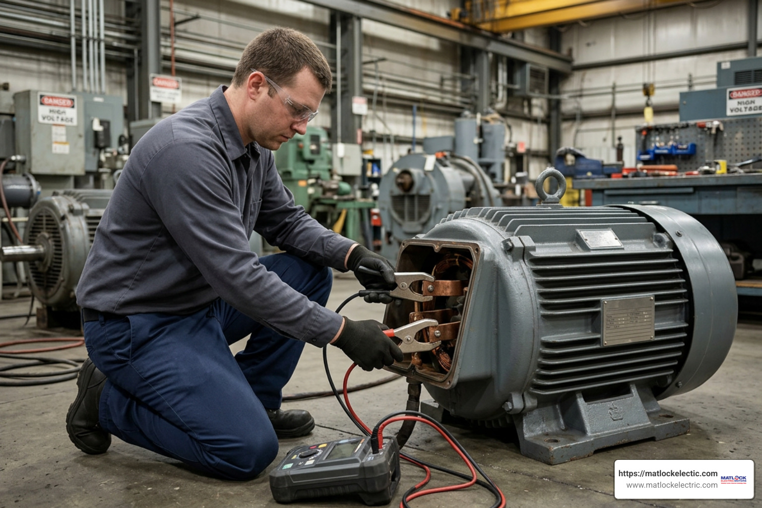
Executing a successful motor winding resistance test requires strict adherence to safety protocols, proper lead placement, and careful observation of thermal conditions. If your equipment requires complex structural teardowns, combining electrical testing with qualified DC Repairs ensures long-term operational integrity.
Pre-Test Safety Precautions and Setup
Electric motor windings are large inductors capable of storing electrical energy. Prior to attaching test leads or energizing equipment, observe the following setup sequence:
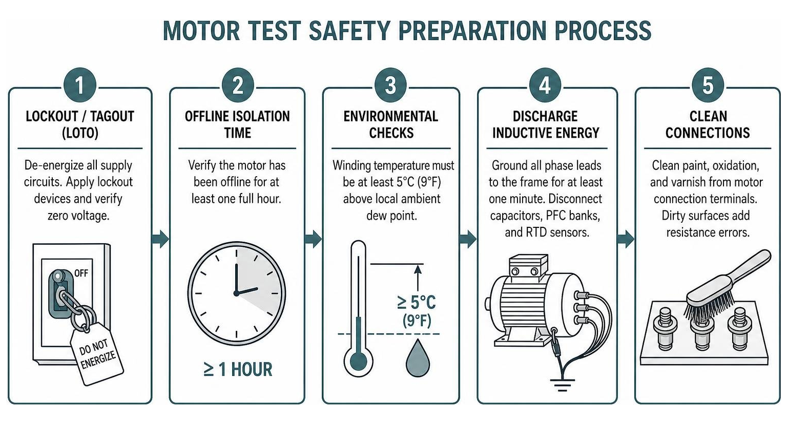
- Lockout/Tagout (LOTO): De-energize all primary supply circuits feeding the motor control center (MCC) or disconnect switch. Apply lockout devices and verify zero voltage presence using a calibrated voltmeter.
- Offline Isolation Time: Verify the motor has been de-energized and offline for at least one full hour prior to testing. This allows internal winding temperatures to stabilize evenly throughout the stator iron.
- Environmental Checks: Inspect ambient conditions. According to standard operating procedures, winding temperature must be at least $5^circtext{C}$ ($9^circtext{F}$) above the local ambient dew point. If condensation forms on motor windings, it alters test readings and compromises insulation integrity.
- Discharge Inductive Energy: Ground all phase leads to the motor frame for at least one minute prior to testing to bleed off stray capacitive and inductive residual charges. Disconnect any surge capacitors, power factor correction banks, or RTD temperature sensors.
- Clean Connections: Use fine emery cloth or a wire brush to clean paint, oxidation, and varnish from motor connection terminals. Dirty terminal surfaces introduce contact resistance errors into micro-ohm test readings.
Step-by-Step Motor Winding Resistance Test Procedure
Once safety protocols are completed and connection points are clean, execute the test following these steps:
- Zero the Test Instrument: If using a portable motor analyzer or micro-ohmmeter, short the positive and negative test leads together and perform a lead zeroing calibration to remove baseline instrument offset.
- Connect Kelvin Clamps: Attach current injection leads to the outer edges of the motor terminal lugs and place voltage sense leads on the inner surfaces inside the current path.
- Configure Test Current: Set the test instrument current output. Apply a DC test current that achieves core saturation without exceeding 10% of nominal motor nameplate current.
- Execute Phase-to-Phase Measurements: Measure resistance across all phase combinations sequentially:
- Reading 1: Terminal $T1$ to $T2$ ($R_{T1-T2}$)
- Reading 2: Terminal $T2$ to $T3$ ($R_{T2-T3}$)
- Reading 3: Terminal $T3$ to $T1$ ($R_{T3-T1}$)
- Allow Reading Stabilization: Wait for magnetic core saturation to stabilize fully before logging readings. Inductive energy absorption can cause readings to drift initially.
- Record Temperature: Measure and record the winding enclosure surface temperature using a calibrated infrared thermometer or internal RTD sensors.
For specialized guidance on portable field testing instruments, technicians frequently reference the operational procedures outlined in the ALL-TEST PRO User Manual, which covers handheld phase resistance and impedance evaluation methods.
How to Interpret Resistance Readings and Environmental Factors

Obtaining raw resistance values is only half the battle. To gain meaningful diagnostic insights, you must analyze phase balance and correct raw values for thermal variation using advanced Technology in Diagnostics.
Calculating Phase Resistance Balance
In a healthy three-phase electric motor, the DC resistance measured across all three phase pairs must be nearly identical. A imbalance across phases causes unbalanced magnetic flux, mechanical vibration, severe current unbalance, and accelerated thermal degradation of motor insulation.
We calculate phase resistance unbalance using the industry standard percentage deviation formula:
$$text{Phase Imbalance (%)} = left( frac{|R_{text{max}} – R_{text{avg}}|}{R_{text{avg}}} right) times 100$$
Where:
- $R_{text{max}}$ is the individual phase measurement furthest from the average.
- $R_{text{avg}}$ is the arithmetic mean of all three phase-to-phase readings: $(R_{T1-T2} + R_{T2-T3} + R_{T3-T1}) / 3$.
Industry standards, including IEEE guidelines, state that phase resistance imbalance must be less than 5% for standard industrial motors, with standard target balance operational thresholds around 2% to 3%. Imbalances exceeding 5% demand immediate investigation prior to returning the equipment to service.
When testing 9-lead AC induction motors, terminal wiring configurations depend heavily on internal winding setups. Detailed diagnostic procedures for identifying internal phase faults across Star (Wye) and Delta configurations are covered in the Diagnosing Motor Winding Faults Guide.
For instance, in a Delta-connected winding configuration, an open coil segment causes the measured resistance across the open terminal pair to read exactly twice the resistance of the two functioning terminal pairs.
Temperature Compensation and Environmental Impact
Copper conductors possess a positive thermal coefficient of resistance. As winding temperature rises, atomic vibrations increase within the copper lattice, impeding electron flow and increasing electrical resistance.
Copper resistance increases by approximately 0.39% per degree Celsius. A temperature rise of just $10^circtext{C}$ ($18^circtext{F}$) increases copper winding resistance by nearly 4%.
To accurately compare historical field readings against factory baseline data or baseline shop tests, raw field resistance readings ($R_{text{measured}}$) must be mathematically corrected to a standardized reference temperature—typically $40^circtext{C}$—in accordance with IEEE 112-2004 standard guidelines.
The temperature correction formula for 100% IACS copper windings is:
$$R_{40^circtext{C}} = R_{text{measured}} times left( frac{234.5 + 40}{234.5 + T_{text{measured}}} right) = R_{text{measured}} times left( frac{274.5}{234.5 + T_{text{measured}}} right)$$
Where:
- $R_{40^circtext{C}}$ is the equivalent winding resistance corrected to $40^circtext{C}$.
- $R_{text{measured}}$ is the raw resistance recorded in the field.
- $T_{text{measured}}$ is the actual winding temperature during testing in $^circtext{C}$.
- $234.5$ is the inferential zero-resistance constant for copper (use $225$ for aluminum conductors).
For comprehensive engineering standards on thermal correction factors and inductive circuit testing, consult the detailed application procedures in the Guide to Winding Resistance Testing and the comprehensive Megger Testing SOP Guide.
Frequently Asked Questions About Motor Testing
What is the difference between an insulation resistance test and a motor winding resistance test?
An insulation resistance test (commonly called a Megger test) uses high DC voltage (typically 500V to 5,000V DC) to measure the electrical resistance between the motor windings and the grounded motor frame. It verifies whether ground insulation is intact, measuring values in megohms ($MOmega$) or gigohms ($GOmega$).
A motor winding resistance test uses low DC voltage and controlled current to measure continuity and phase balance through the copper conductor wire coils themselves. It measures very low resistance values in ohms ($Omega$), milliohms ($mOmega$), or microohms ($muOmega$). A motor can easily pass a 2,000 $MOmega$ insulation resistance ground test while containing a severe inter-turn short circuit that renders it unusable.
What percentage of phase imbalance is acceptable during testing?
According to NEMA, IEEE 1415-2006, and CSA standards, phase resistance imbalance between phases should ideally remain under 2% to 3%. A phase imbalance of less than 5% is generally considered acceptable for older field equipment. Any resistance imbalance exceeding 5% indicates a distinct fault—such as shorted turns, broken parallel strands, or severe contact oxidation—and requires physical repair before putting the motor back into operation. Imbalances over 10% represent definitive coil failure.
Why does a standard multimeter show zero ohms on large motors?
Large industrial electric motors (such as a 200 HP, 460V motor) are wound with very thick copper wire or parallel copper bars. Their internal DC winding resistance is extremely low, often dropping below $0.01 Omega$. Standard handheld multimeters lack the measurement resolution to display milliohms and cannot zero out the inherent resistance of their own test leads (which typically range from $0.1 Omega$ to $0.3 Omega$). As a result, standard multimeters register these ultra-low resistance paths as zero ohms. Accurate testing requires a micro-ohmmeter or DLRO utilizing 4-wire Kelvin connections.
Conclusion
A regular motor winding resistance test is one of the most effective, straightforward diagnostic tools available for maintaining rotating electrical machinery. By catching early signs of phase imbalance, multi-strand blowouts, high-resistance terminal connections, and thermal insulation breakdown, you can prevent unexpected motor failures, lower energy costs, and extend operational lifespans.
Integrating routine resistance checks into your overall predictive maintenance strategy keeps your critical motor systems performing at peak efficiency. Whether you need field testing, precision rewinding, or complete equipment overhauls, our specialized team provides comprehensive maintenance solutions tailored to your operational needs.
If your facility requires expert electrical diagnostics, emergency repair, or new equipment sourcing, explore our complete line of industrial Electric Motors or schedule comprehensive diagnostic evaluations with our experienced service team today.